
The Yardmmaster II (ATCS) Automatic Train Control System
The Central Okanagan Railway Company needed a 100% reliable system that ran three trains in the Peachland Museum, on demand, and without the need for a supervisor. A visitor pushes a button, three trains leave their station and proceed to the next station where they stop and wait for the next “GO” command.
This was necessitated by the age, and parts availability, of an old mechanical relay sequence that had worked very well but only operated two trains. The upgrade simply needed three.
The first edition, June 2013, consisted of three Yardmasters installed as directed by the manufacturer. A full year of trying, and with a lot of help from the designer, was deemed unsuccessful. Our building was simply unfriendly. There was very poor wiring that supported a great deal of EMI and large windows consistently interfered with infrared detectors. The system was moved and reconfigured time and time again and the Yardmasters were even returned for upgrades on a number of occasions. In the end it was simply set aside as a failure.
1. – The first and second installations didn’t work
During the following year, we tried a DCC/DC system that needed no high tech wiring and no infrared or photo sensors. All of our engines were programmed not to operate on DC. Trains would run when DCC was applied to a stopping area and when the trains left, plus a timed 20 seconds, the DC would be reapplied stopping the next train that arrived at the station. The system should have worked but the DC/DCC/DC switching played havoc with every train on the layout. They often stopped and started pretty much as their feelings moved them.
In the end, and in frustration, we delved into the guts of the old Yardmaster to see how they actually worked and John Kirby came up with a interconnection plan that seemed to do the job reliably “on the bench”. As well, high tech multi shielded cables were properly installed reducing the IMI to less than 5% of the original and we attacked the issue again.
2. – Bench tests determined the inner workings.
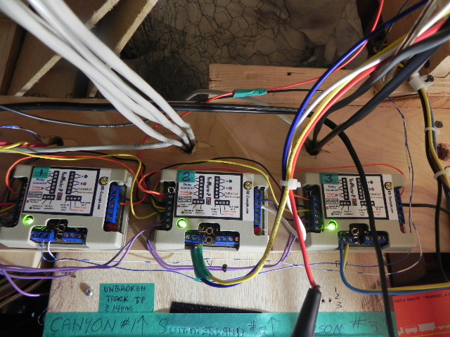
Modern, reliable, infrared pairs were reinstalled in the three locations, and we used MRD1 drivers to interface between the sensors and the Yardmasters. It worked. The sensors and the Yardmasters clearly understood each other 100% of the time. We had a beginning.
3. – New installation – new location
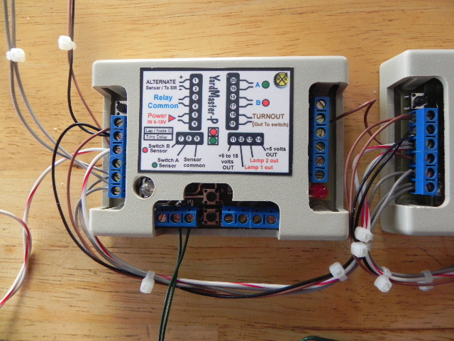
And so to ‘count’ the trains, should there be an accident somewhere on the layout, the visitors GO button would have to be disabled until all trains were safely home. Not as easy as it seems because the Yardmasters were not equipped with the AND function nor it seemed any output that would suffice. This time there was no help from the Yardmaster engineers.
As it turned out that the DCC input to the Yardmaster not only switched the DCC signal to the track on one pin, it also turned off the DCC signal at another. If a train was ‘in the station’ when the GO was pressed DCC would be applied to pin 18 and removed from pin 20. I could use that simple logic because the DCC signal is actually an AC voltage with the code riding on it. Simply rectify that extra AC and use the + DC voltage to turn on and off 12 VDC relays.
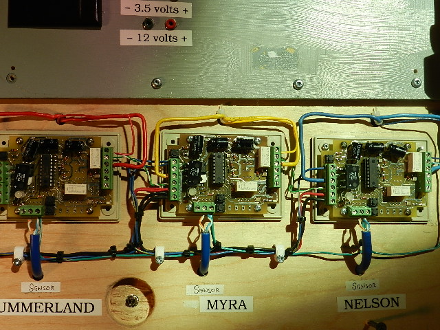
We bought three small voltage A-230 regulators from China for $10.00 CDN. Delivered. They use the 14.4 VAC (The command control signal) to provide an adjustable 11.2 VDC output to the relay coil. They come with two pairs of contacts. One would be in series with the GO button circuit and the other would feed 3.5 VDC to a bright green LED on the GO button.

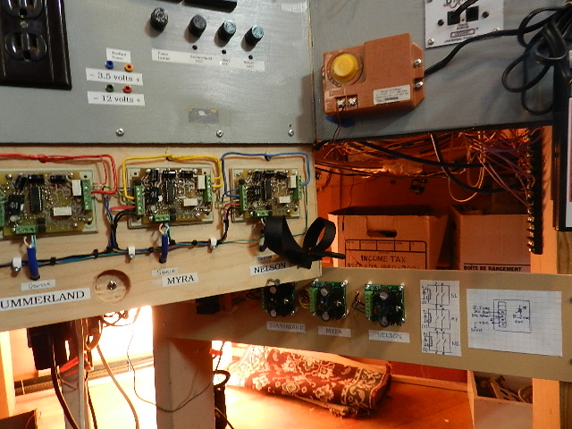
4. – AND relays and regulators.
When the GO button is activated DCC applied directly to the second or ‘far’ track at each station. The DCC signal for the near track is switched on through the Yardmaster. The Yardmaster turns RED and the trains start to move out. When the caboose, or EOT passes the detector the Yardmaster turns BLUE and the AND cct opens. When the next train hits the sensor again the Yardmaster turn GREEN, the DCC is removed from the near track and a relay is closed again. After three relays are closed the GO is rearmed.
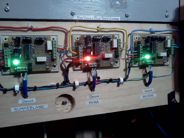
5. – Two trains in – one out on the main.
It was agreed that the administrator should be able to easily see the LED signaling rather than have it all put neatly away under the layout. Should a problem develop, and it surely will, he can identify the area right away and see it.
6. – Everything is handy for the museum staff.
Should a coupler become disenchanted with the work the next train through will simply move the lost train into a stopping block. Should a engine pick at a switch, sadly the most likely issue, the Yardmasters will show where it happened and it can be put back on te track. It will move forward right away and finish the Yardmaster sequence.
So there we go. After two years of fooling around we have a very reliable public display. Yes. There are computer friendly systems being used on big layouts. They can run an unlimited number of trains into and out of an unlimited number of stations. They cost money and in every case I know of, require a specialist who does nothing else. What’s more, all these high tech systems were built, as new, while our layout was, and is, a 20-year-old creation morphing time and time again into something bigger and better.